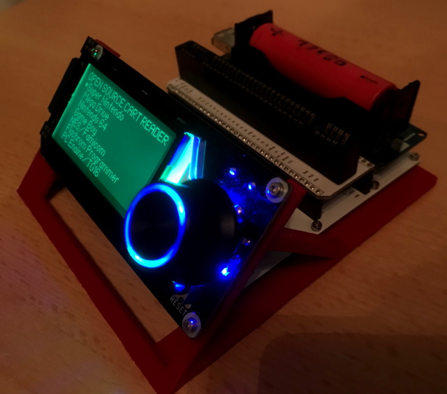
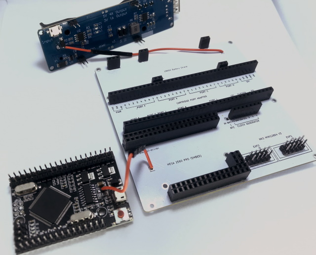
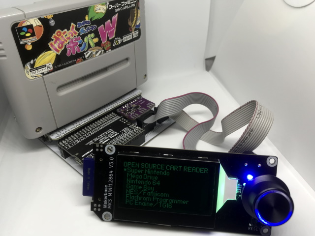
The Open Source Cartridge Reader consists out of different modules that need to be modified or assembled from parts.
Attention: You need to wear safety glasses during this build.
Flashing the Arduino
Before you start with the build you should make sure you have everything set-up correctly to flash the Arduino code. To test this plug the unmodified(SMD fuse not removed yet) Arduino Mega into your PC and upload the code as described here.
Info: Once you removed the SMD fuse from the Arduino it will no longer turn on on its own and from there on will need the main PCB with a cartridge slot adapter PCB attached to receive power. So it's best to flash it at least once before you de-solder the fuse.
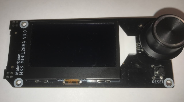
LCD module
Attention: It's important that you use exactly this LCD module since there are many similar looking modules that are however build differently.
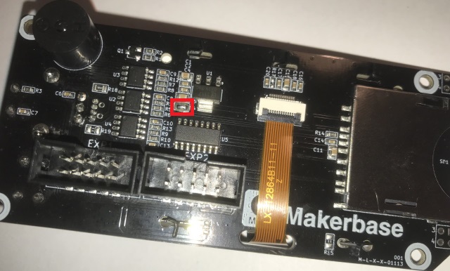
Here you only need to close a little jumper using some solder. Just apply fresh solder to both pads and then add a little more to the middle while heating both pads with your soldering iron.
Info: This allows the 3.3V generated by the AMS 1117 voltage regulator on the LCD module to be used as a power source for the Cart Reader PCB.
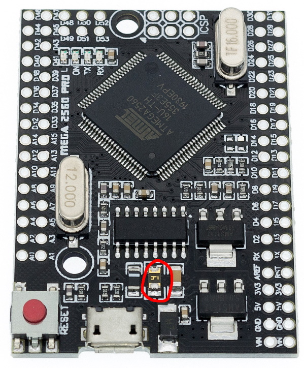
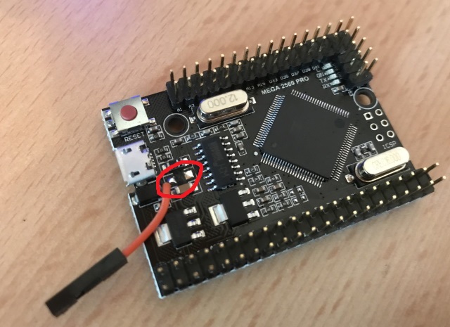
Arduino compatible Mega 2560 Pro (embed)
Attention: After this modification the Arduino will only work together with the Cart Reader and not on its own anymore.
You need to remove the SMD fuse and solder part of a dupont wire to the left pad of the now removed fuse. To remove the fuse just put fresh solder to both ends and then quickly heat up both ends in an alternating pattern with your soldering iron until the fuse just wipes off. Make sure the pads are not connected together and that the wire only touches the left pad. Next you have to solder all the male pin headers but leave out the 6-pin ICSP header like shown in the picture.
Before:
After:
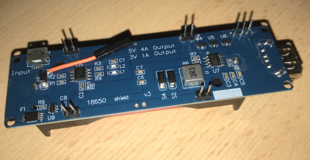
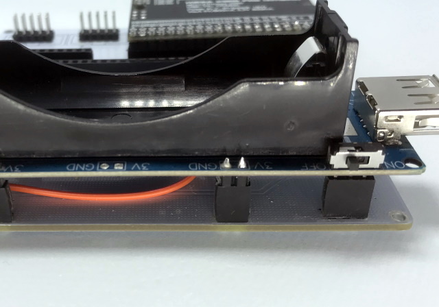
Battery module
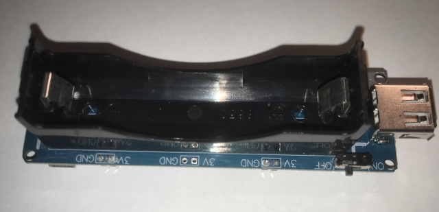
You need to solder four 1x2 male pin headers and also snip of the legs of the power switch and extent the remaining solder stumps using three single pins cut to size so the final assembly will have the same height as all the other pin headers. Lastly you have to solder another dupont wire behind the diode.
Attention: Wait with inserting the battery into the battery module until you have completely assembled the Cart Reader. Beware of the polarity!
Info: The Cart Reader will not turn on if no battery is inserted.
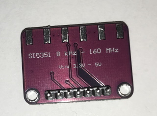
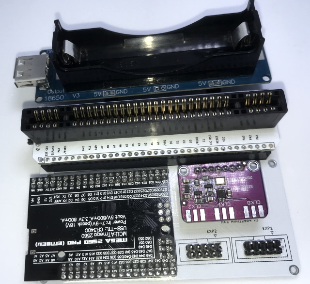
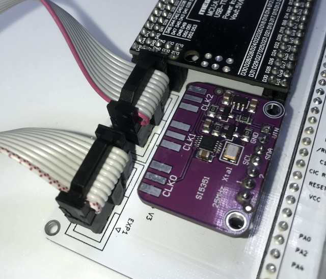
Clock generator
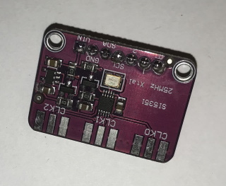
Here you only need to solder a 1x7 male pin header.
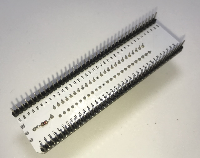
Main board
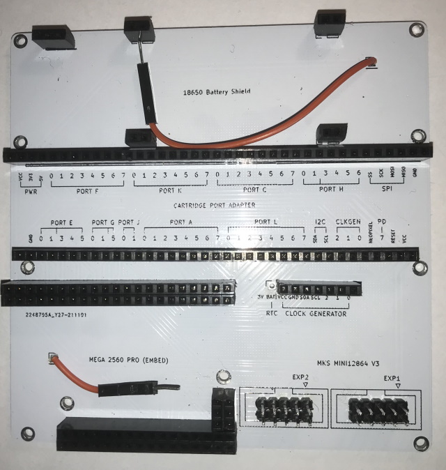
You need to solder quite a few female and male pin headers and two more dupont wires.
Info: If you have a Dremel tool with a cutting disc this makes cutting the female pin headers to size very easy.
Attention: Make sure you align the 1x7 female pin header for the clock generator correctly, the leftmost pad labeled "3V BAT" does not get connected. Also don't use an 1x8 pin header instead of the 1x7 since eventually you will plug the clock generator in the wrong way by accident which will result in the clock generator to be dead.
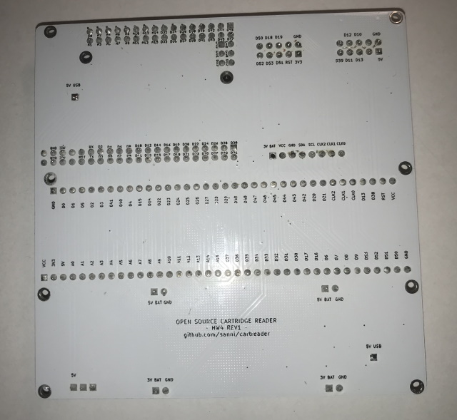
Info: The silkscreen on the top side tells you the pinout of the 1x38 and 1x36 pin headers using the port numbers of the Atmega 2560. The silkscreen on the back side tells the pinout using the Arduino pin numbers.
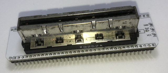
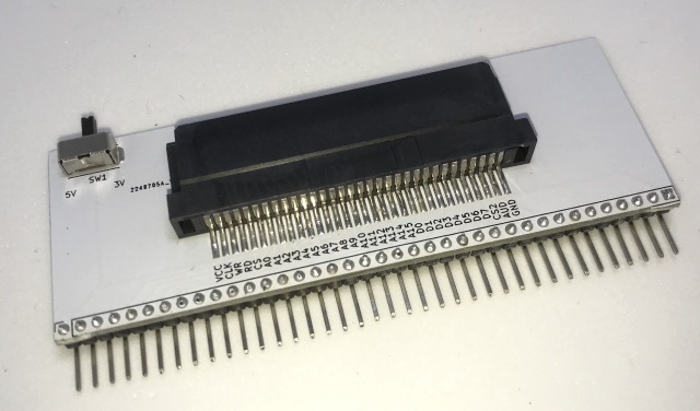
Cart Slot Adapters
On each adapter PCB the cart slot sits on the side that says e.g. "2.5mm 50-Pin N64 Cartridge Slot". It will not work if you attach the slot to the wrong side of the PCB.
The cart slot adapter PCB selects the needed voltage therefore the Cart Reader does not turn on without an adapter PCB inserted.
Info: The silkscreen on the top side tells you the cart slot pinout. The silkscreen on the back side tells the pinout of the 1x38 and 1x36 pin headers instead.
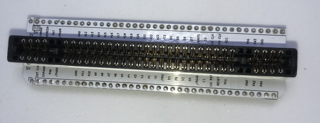
SNES adapter
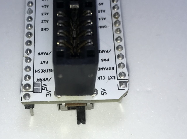
The SNES slot can be equipped with a slide switch to change the voltage between 3V and 5V for backwards compatibility with older cartridge slot adapters.
If you just want to read/write SNES cartridges you can leave the switch off and instead bridge the 5V solder pad next to it to permanently supply 5V.
If you do install the slide switch its legs need to be cut before soldering so that they don't stick out the other end and it gets mounted on the backside.
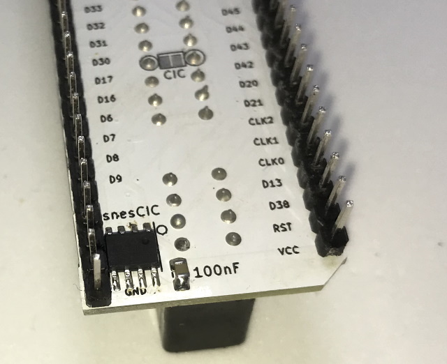
There is also a spot to solder a snesCIC for better SA1 unlocking. But you can also unlock SA1 by bridging the CIC solder pads instead, it just might take a few more tries.
Parts:
- SNES slot
- two 1x40 male pin headers
- slide switch (optional)
- PIC 12F629 flashed with snesCIC (optional)
- 100nF capacitor (optional)
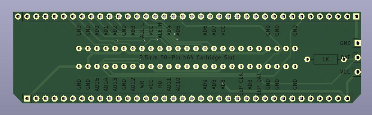
N64 adapter
The resistor for the controller cable needs to be placed on the backside.
Parts:
- N64 slot
- N64 controller extension
- 1k resistor
- two 1x40 male pin headers
GBx adapter
The GBx adapter has a slide switch so you can select 3V for GBA and 5V for GB(C) modules.
Parts:
- GBx slot
- slide switch
- 1x40 male pin header 90°
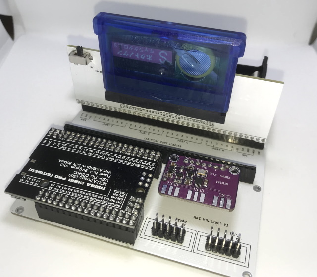
Final assembly
Insert the battery at the very end after you plugged in all other modules. Then plug in an USB cable into the Arduino and charge the battery a little to "unlock" the battery module.
Warning: Only use a high-quality battery with integrated protection circuit you bought from a reliable vendor. Check for short-circuits in your soldering work before inserting the battery. Never insert the battery into the holder the wrong way. Never charge the battery without supervision.
Make sure the little bump on the connector matches the footprint on the PCB. EXP1 on the LCD needs to be connected to EXP1 on the main PCB and EXP2 to EXP2.
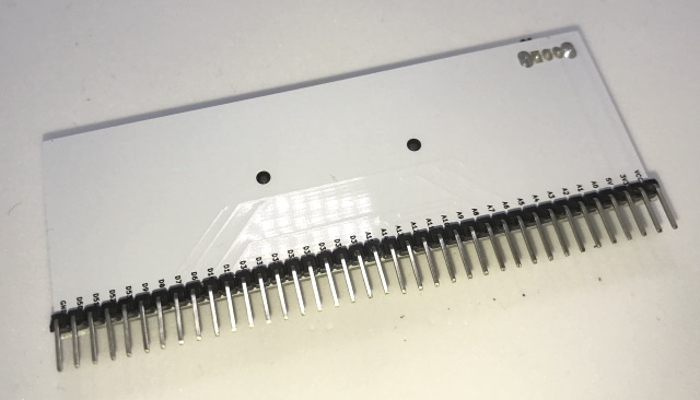
simple 3D printed frame (optional)
This is a frame that hold everything together. But you can also put the Cart Reader in a shoe box or similar.
The frame uses the LCD adapter PCB to mirror the LCD connector's pinout vertically(by moving it to the backside) and thus allows the LCD module to directly plug into the main PCB.

Info: This is the top side that points up.
Attention: You have to solder the pin headers at an angle.
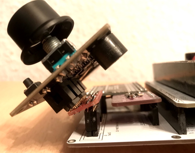
You can also shorten the wires included with the LCD instead of using this PCB.
The modules get fixed to the frames with a couple of M2x6 screws.