The Open Source Cartridge Reader consists out of different modules that need to be modified or assembled from parts.
Note: This build guide is based on Revision 3 of the HW5 main pcb but you can build Revision 4 the same way by ignoring the Vselect SMD part footprints on the front side as the Vselect build needs more complicated soldering.
Build videos:

Written Build Guide
1) Flashing the Arduino
Before you start with the build you should make sure you have everything set-up correctly to flash the Arduino code. To test this plug the unmodified(SMD fuse not removed yet) Arduino Mega into your PC and upload the code as described here. This is also a good time to visually inspect the Atmega2560's pins. There have been cases where pins on the chip were bridged or even broken off from the factory.
Info: Once you removed the SMD fuse from the Arduino it will no longer turn on on its own and from there on will need the main PCB to receive power. So it's best to flash it at least once before you de-solder the fuse.
2) LCD module
Attention: It's important that you use exactly this brand of LCD module since there are many similar looking modules from other brands that are however built differently.
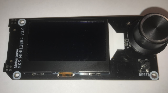
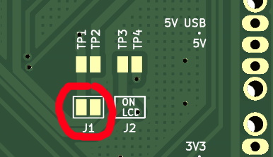
Here you only need to close a little jumper using some solder. Just apply fresh solder to both pads and then add a little more to the middle while heating both pads with your soldering iron.
Info: This allows the 3.3V generated by the voltage regulator on the LCD module to be used as a power source for the Cart Reader PCB and the Mega 2560 Pro.
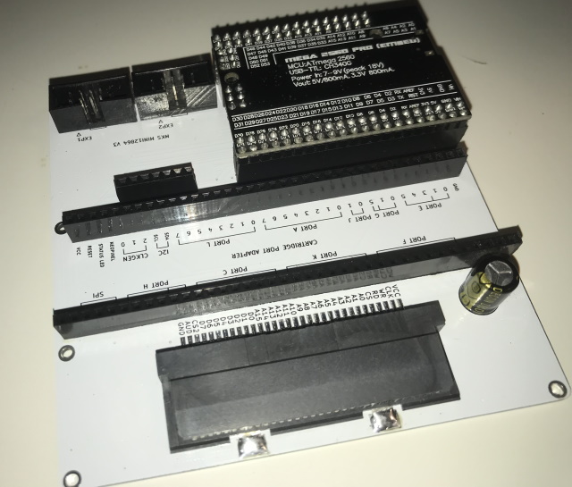
3) Arduino compatible Mega 2560 Pro (embed)
Attention: After this modification the Arduino will only work together with the Cart Reader and not on its own anymore.
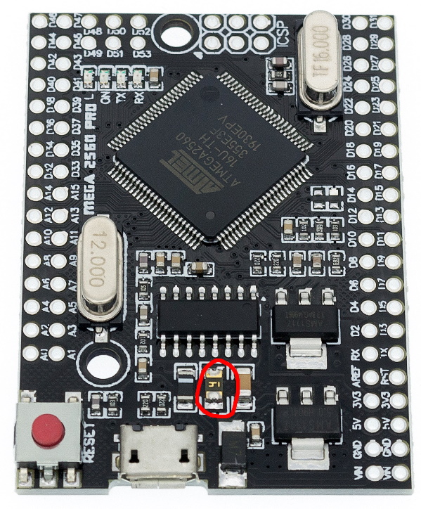
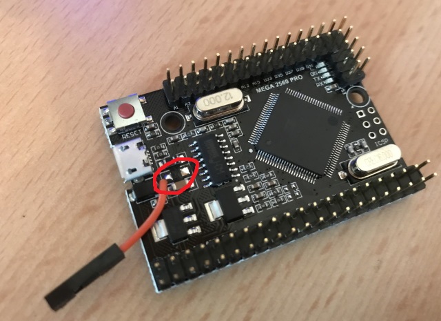
You need to remove the SMD fuse and then cut a female-to-male dupont wire in two and solder one half to the left pad of the now removed fuse. Instead of the dupont wire you can also use any wire(~24AWG) you have.
To remove the fuse just put fresh solder to both ends and then quickly heat up both ends in an alternating pattern with your soldering iron until the fuse just wipes off. Make sure the pads are not connected together and that the wire only touches the left pad.
Info: This mod is needed so that the Cart Reader can switch the Mega 2560 Pro's supply voltage between 5V and 3.3V and thus guaranteeing that the proper voltage levels are supplied to the address and data pins.
Next you have to solder all the male pin headers like shown in the picture.
Before:
After:
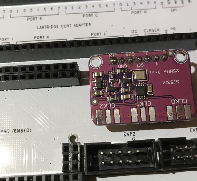
4) Clock generator
Info: The SI5351 Clock Generator provides a clock signal for SNES SPC7110/SA1/SF Memory/Satellaview cartridges and N64 cartridges with EEPROM saves.
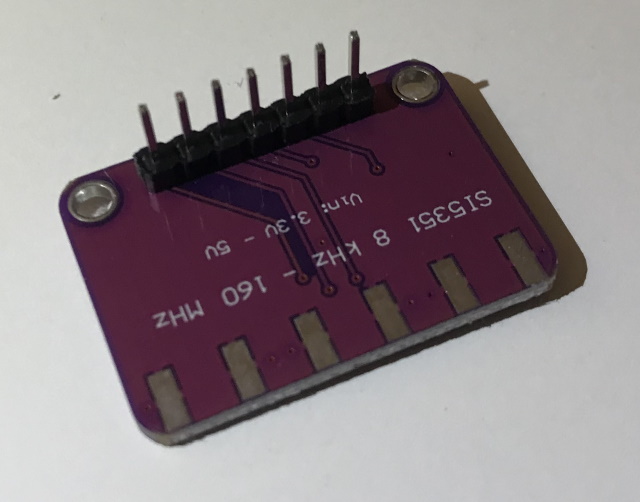
Here you only need to solder a 1x7 male pin header. Be sure to solder it the right way around like in the pictures, it won't work upside down.
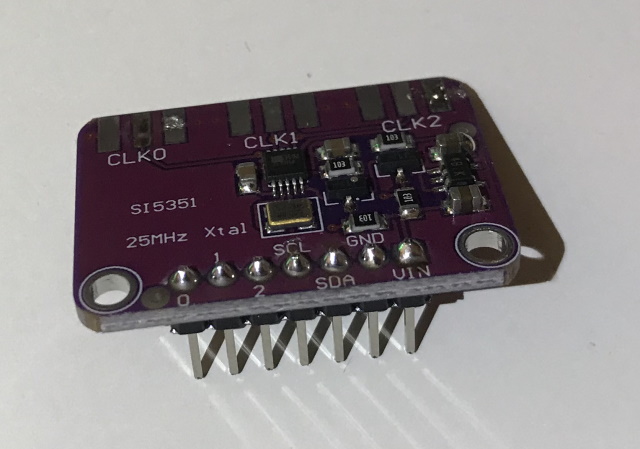
Info: The Cart Reader will work without the clock gen, you just have to disable it in the HW Config found in Cart_Reader.ino by removing the line "#define clockgen_installed". Ofc the aforementioned SNES cartridge types will not work without it.
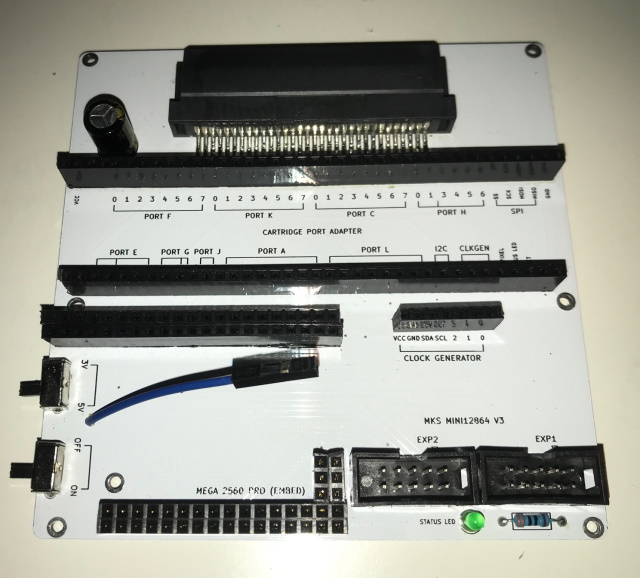
5) Main PCB (HW5)
The GBA slot should be soldered first because it's the hardest part. Next you need to solder quite a few female pin headers. Since you most likely didn't get them all in the correct size remove the pins that you don't need with pliers and then cut off the excess plastic either with a side cutter, box cutter or a Dremel with a cutting disc.
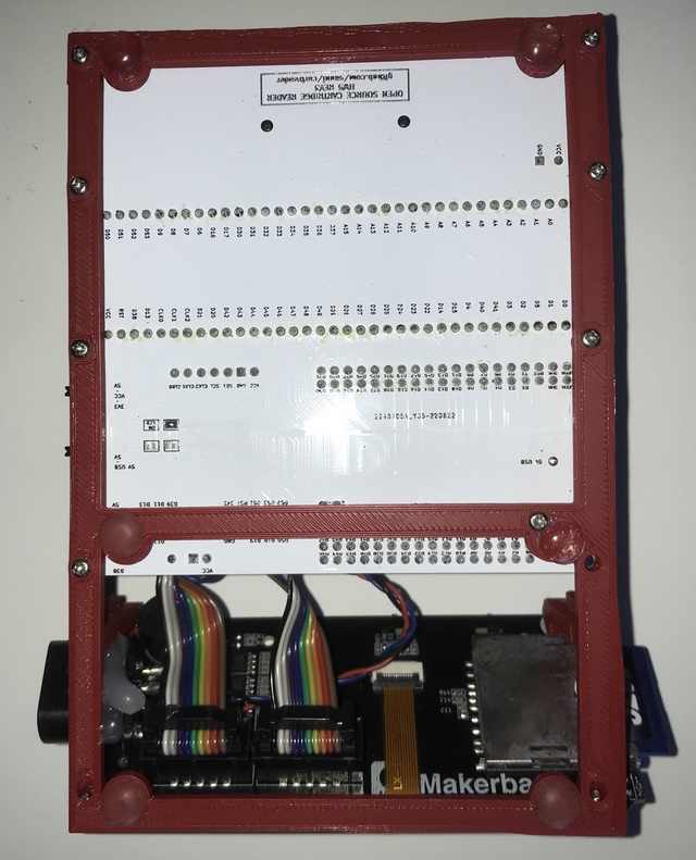
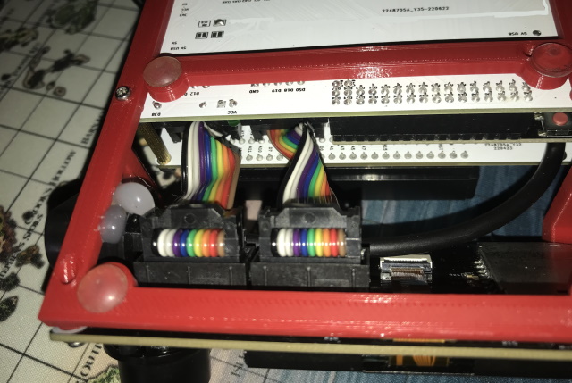
Now solder the two IDC box headers for the display connection. As an alternative you can also use 2.54mm male pin headers.
Then solder the second half of the dupont wire and also the two switches. Do not operate the switches while they are still hot from soldering, wait until they have cooled down completely.
Note: If you will be using VSelect (automatic voltage selection) DO NOT install the voltage switch. Some kits only include a single switch to help avoid this mistake.
The 470uF capacitor is optional but recommended especially for SNES SA1 games. At the front is a spot to solder a 3mm status LED together with its resistor(1K for green LED, 220 Ohm for blue, or anything in between). This is also optional. Inside the LED bulb there is a big metal thing and a small metal thing connected to the two legs. The leg that is connected to the big metal thing needs to be soldered to the square pad on the PCB.
NOTE: If you will be using VSELECT (which means you won't be installing a voltage switch) DO NOT install the LED/resistor. Some kits do not include them to help avoid this mistake.
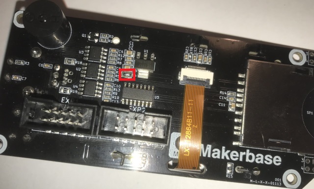
If you have an older version of the main PCB (prior to Rev.5) you also need to close the solder jumper marked in red on the back of the main PCB.
6) The first test
By now you have built everything to dump Game Boy (Color) and GBA games and it's time for a first test.
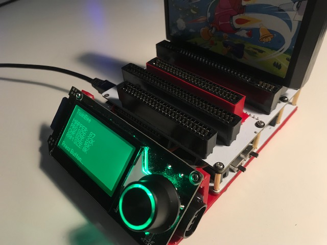
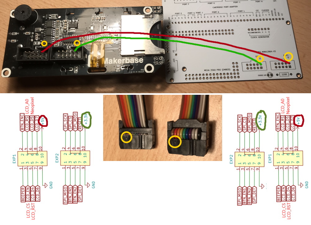
Attach the LCD screen with the included wires to the main PCB.
Then switch the voltage to 5V, insert your SD card with the files from the SD folder copied to its root, plug in an USB cable and switch the Cart Reader on. You should be greeted by the main menu that you can scroll through using the knob on the right.
Switch the Cart Reader off again, insert a Game Boy (Color) game and try to dump it. If the dump was successful continue with building the six slot adapter PCB.
7) six-slot adapter PCB
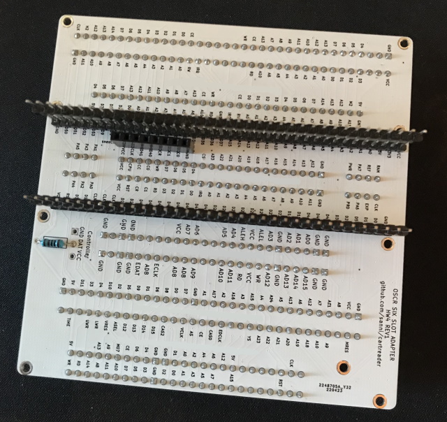
You should start by soldering the SNES slot followed by the 1K resistor, the 1x8 female pin header and the 1x38 and 1x36 20mm male pin headers and then continue with the remaining 5 cartridge slots.

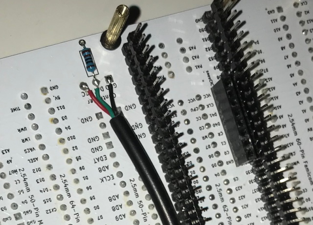
The N64 controller socket or extension cable gets connected through some wires to the VCC, DAT, GND pins. Don't stick the cables into the holes or you will have to bend them 90° which will weaken the cable until it will one day snap. Instead treat the holes like SMD pads and solder the cables lying flat against the PCB.
And then in the case of the socket hot glued to the frame somewhere. If you are using the extension cord instead use some zip ties to fixate the cable to the frame.
Info: All slots are wired in parallel so if you make a soldering error on one slot it's very likely to affect all slots.
8) PIC_adapter PCB for snesCIC
Solder the PIC12F629 flashed with snesCIC, the 100nF ceramic capacitor and an 1x8 2,54mm pin header to the PIC_adapter PCB like so:

The finished PCB fits underneath the SNES slot on the six slot adapter PCB.
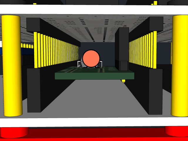
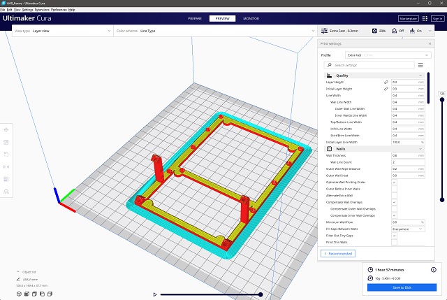
9) 3D printed frame
The simple frame can be printed with Cura's default extra fast profile, PLA as material choice works great. Kytor also has a fully enclosed case that is available to download and print.
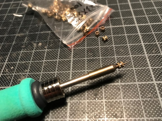
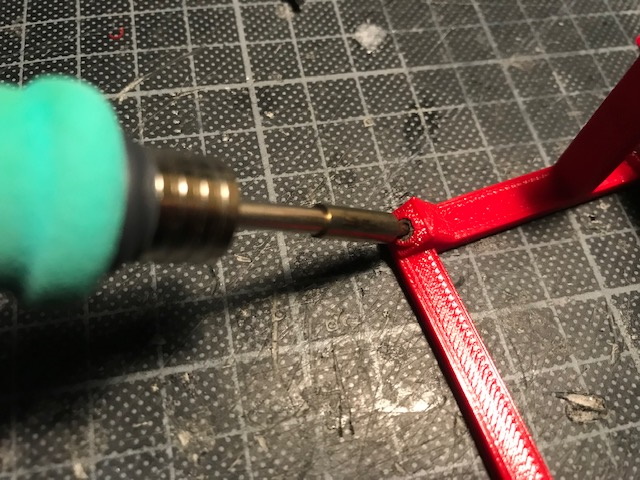
Use your soldering iron with a fine pointy tip to insert 4 brass threaded inserts into the display holder.

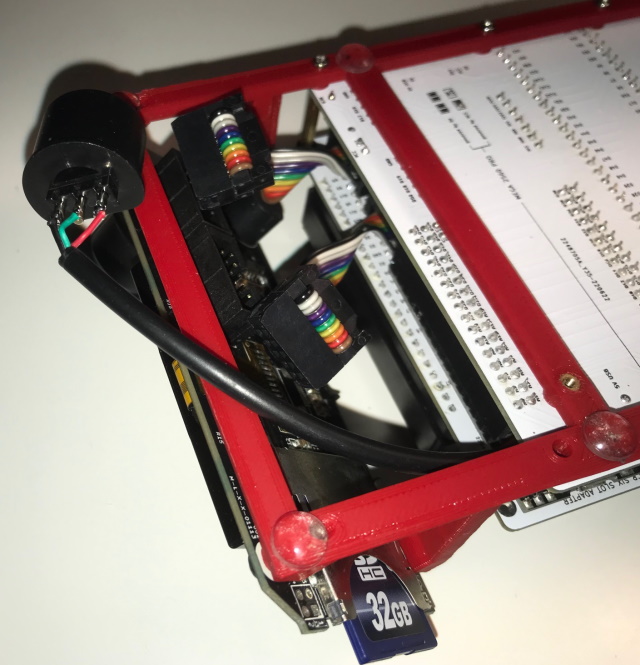
10) Final Assembly
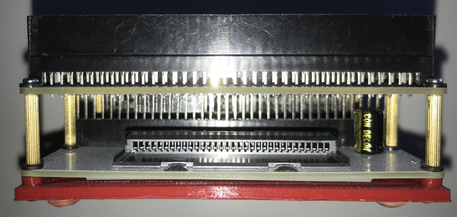
Use the screws and the eight 18mm spacers to connect both PCBs and the display to the frame. Put a washer between the screws and the PCBs to prevent scratches.
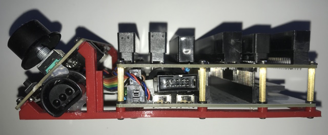
In my case the Aliexpress seller send me 17mm spacers instead of the ordered 18mm so I had to add an additional washer. One of the 18mm spacers goes through the Mega Pro's PCB, it is a bit fiddly to align.

I had to use the 3d printed N64 sleeve because the Aliexpress seller send me a 2,54mm Master System slot instead of the 2.5mm N64 slot. It still works since the N64 sleeve will center the cartridge so that the pins make contact even though the pitch is slightly off.

If you have the correct 2.5mm slot you don't need the 3d printed sleeve.

GBA Slot in the back.
I have shortened the display cables to make it look tidier but you can also leave them as is and just stuff them in the space underneath the display.
Be aware that both display cables twist 180 degrees.
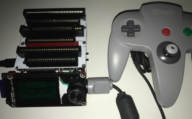
11) Self Test
Now that everything is build you should do the self test you can find on the second page of the main menu.
It checks if the pins are shorted either to GND or to each other. It also checks the 1K resistor and activates the clock generator.
You can learn more about the self test here.